![[Translate to English:]](/storages/rst-etit/_processed_/e/8/csm_Technologie_RST_2018_339_4acb56a732.jpg "[Translate to English:]")
TUDOR (TU Dortmund Omni-elastic Robot)
Next generation robots physically interact and operate with humans in the same work place. The human creativity, learning and adaptability are perfectly complemented by the robots’ strength, precision and endurance resulting in versatile production systems which are economical even for small and medium batch sizes.
With demographic trends forecasting an increase in aging population in many countries, efficient service robots assure independence for those physically weak and aged to organize their everyday lives.
So far, there has been limited interaction between trained professionals and robots even in structured and monitored work environments. The reason lies in the currently prevailing rigid and massive industrial robotic arms. These rigid robots guarantee high precision and controllability even under extremely large payloads. Looking at the other side of coin, massive robotic arms consume high energies and require extremely powerful links, actuators and transmission systems. More critically, they introduce high injury potentials in environments where humans and robots work together. Additional sensing mechanisms and safety systems add to the already high manufacturing costs.
This is where lightweight but flexible robots come in handy. The deliberate integration of elastic links in the kinematic chain results in robots which are highly energy efficient, require less powerful actuators and transmission systems, can achieve rapid accelerations, have low material costs and have higher payload to weight ratios, thanks to their light-weight structures. The injury scenarios projected by light-weight robot arms are also inconsequential when compared to those by their rigid bodied counterparts. The intrinsic compliance provides potential to absorb impact energies and allow for the sensing of contact situations and development of reaction schemes.
The main disadvantage of flexible robots results precisely from their flexibility. Long lasting oscillations could arise from their own maneuvers or from external disturbances. Steady state offsets could result due to sagging of the structure under high payloads. The dynamics of the system change considerably with robot pose and payload. Similar challenges arise in, for example, fire rescue turntable ladders, concrete pumps and long reach inspection robots for hazardous environments. This research project deals with fundamental issues in modeling and control of multi- elastic-link robot arms. Development of concepts to: control motion and damp oscillations, detect accidental contact situations, device appropriate response strategies and to use passive and active compliance to absorb collision impacts, is the overall objective of the research project.
The experimental system: TUDOR
To implement experimental tests for the project, a modular experimental set-up, TUDOR (Technical University of Dortmund Omni-elastic Robot), shown in Figure 1(a), was developed in the Institute of Control Theory and Systems Engineering
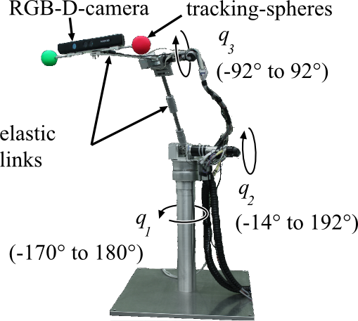
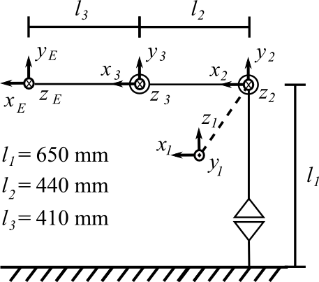
Figure 1: The experimental system TUDOR (a) and the corresponding equivalent rigid body kinematics (b).
Construction
TUDOR is a 3 DOF robotic arm which comprises of three brushless DC motors with planetary gears and ceramic quadrature encoders. The first actuator with the joint variable q1 is installed on the cylindrical base, and rotates the arm structure in the horizontal plane around the axis z1. The mechanical connection between the first and second joint is considered to be the rigid first link of the robot. The second and the third joints have horizontal rotary axes with q2 about z2 and q3 about z3. Both actuators are interconnected via the elastic second link. The elastic third link is connected to the third actuator.
Selection of suitable materials and dimensions offers possibilities to vary the natural frequencies, directions of oscillation and natural damping characteristics of the structure. The elastic arm is made of either aluminum or spring steel beams. Figure 1 (a) shows a common configuration of the experimental system. The equivalent to rigid body kinematics in the neutral joint position is shown in Figure 1 (b).
Sensor Systems for Control
Like the links, the sensor systems installed on TUDOR are also modular interchangeable. Strain gauge pairs in half –bridge circuits are installed on TUDOR, as shown in Figure 2 (a). To further investigate the potential and limits of modern fiber-optic sensors, Fiber Bragg Grating (FBG) sensors can be additionally fitted. The strain gauges as well as the FBG sensors distributed along the arm are used to detect the occurring structural oscillations and static bending. With a single fiber, several measuring points along the structure can be realized which reduces the amount of wiring required in comparison to that for strain gauge circuitry. FBG sensors use optical measurement principles (illustrated in Figure 2 (b)) which are immune to electromagnetic interferences.
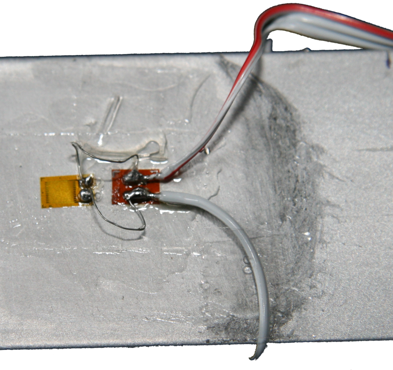
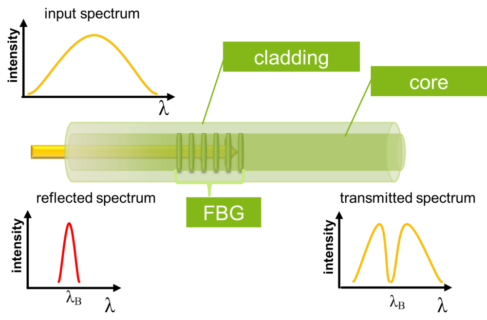
Figure 2: Strain gauges installed on the TUDOR link (a) and the principle of operation of the alternatively used Fiber Bragg Grating sensors (b).
In addition to the strain sensors, TUDOR is equipped with two different camera systems. The first camera can be mounted on the end of the third link in an eye-in-hand configuration. It is a so-called "intelligent" camera with an integrated power PC, so that the image processing can be performed directly on the camera system. The preprocessed image information is further processed in the real-time operating system for the robot control. The resolution of this camera is 1024x768 pixels at a frame rate of up to 39 frames per second. The second camera, mounted on a wall, is a Kinect RGB-D sensor which provides depth images (D) in addition to conventional RGB images with 640x480 pixels resolution.
Reference Sensors
A stereo camera system with a base length of 3 m is attached on the laboratory ceiling, as shown in Figure 3. It is used for evaluation of the modeling and control concepts developed in this research project, as well as for recording system identification data. The centers of two spheres (one red and the other, green) mounted on either side of the end effector are tracked during the robot movement at a frame rate of 50 Hz with a resolution of 640x480 pixels for each camera. Within the robot work space, tip position measurement with an average accuracy of 2.0 mm is obtained.
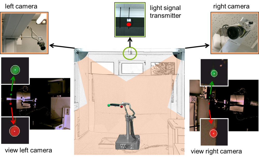
Figure 3: TUDOR in the laboratory within the field of view of the stereo camera system (bottom center). Views of the left (bottom left) and the right (bottom right) cameras with the detected centers of the measurement spheres. The light signal transmitter (top center).
In addition to the stereo camera system, a light signal generator is mounted directly above TUDOR which is triggered by the real-time operating system of the robot. In the images of the camera, the light pulse is detected so that the data processing delay time of the entire sensor setup and plant can be determined.
Research Results
Strain-based oscillation damping
This mode of oscillation damping is based on independent joint control. For this, the robot arm is viewed as a chain of independent modules, each module with one drive and one link. The nonlinear dynamic coupling between these modules is conceived as disturbances. Similarly, the feedback of the vibrating elastic arm on the actuator shaft can be neglected
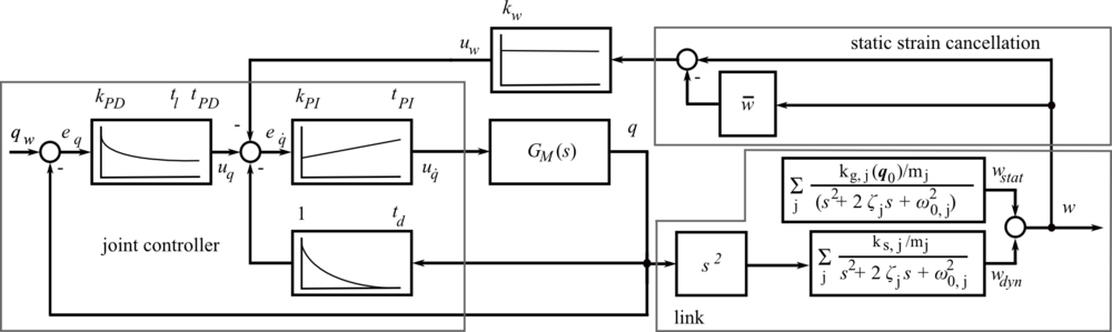
For each module, a controller is designed according to the architecture shown in Figure 4. GM(s) is the first order linear transfer function of the actuator considering viscous friction. For this purpose, a cascaded controller is designed consisting of a PI velocity controller and a PD position controller according to the symmetrical and absolute optimum values.
The link deflection, w, is measured using the strain sensors and the nonlinear static part of the strain is canceled by subtracting the moving average from the actual measurement. With the static strain canceled, Evans root locus is used to design a proportional strain feedback for the cascaded joint controller. The feedback shifts the complex conjugate poles of the link structure into regions of greater damping within the Laplace plane. In this way, in addition to motion-induced arm oscillations, oscillations which result from the interaction with the environment are also damped. The oscillation damping is demonstrated in the video below:
Video: Model free vibration damping of a multi-link flexible robot arm.
End effector positioning in the presence of varying payloads
The analytical modeling of the configuration and load-dependent deflections of the elastic links under the influence of gravity is extremely complicated. Therefore, within the framework of the research project, the forward and inverse kinematics under the influence of gravity are modeled through various data-based approaches. The training data for these models, which cover varying load configurations for the whole workspace, have been acquired using the stereo camera system. The forward model predicts the target pose given the joint angles and the strain signals while the inverse kinematic model predicts the joint angles required to assume a target pose.
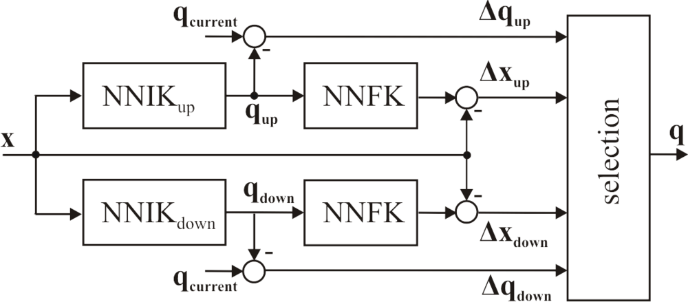

Figure 5: Inverse kinematics design (a) with an artificial neural network each, for the inverse and the forward kinematics of the elbow-up and elbow down configurations. The experimental validation (b) of the positioning using the stereo camera system.
For the study of different monitored learning approaches, the arm kinematics are modeled using linear regression, Local Linear Model Trees (LOLIMOT), Radial Basis Function (RBF) networks and Multi-Layer Perceptron (MLP) network based on the analysis of the rigid body kinematics and transformation of the original features onto suitable non-linear features. As shown in Figure 5 (a), models are developed for both forward kinematics and inverse kinematics in the elbow-up and elbow-down configurations. This is necessary to resolve the conventional ambiguity of robotic arm inverse kinematics. The experimental validation (Figure 5 (b)) confirms an average pose error of less than 3 mm.
The video below documents the inverse kinematics control with varying payloads up to 600 g:
Video: Inverse kinematics control with artificial neural networks in the presence of varying payloads.
A data-based inverse kinematics control in combination with the previously shown oscillation damping serves as a basis for a ball catching demonstrator developed in the Institute of Control Theory and Systems Engineering. A pitcher throws several balls consecutively to the robot from a distance of 6 meters. The RGB-D camera mounted behind the pitcher is used for the detection of the thrown balls. From the ball positions in successive frames, the trajectories of the balls are estimated on the basis of an extended Kalman filter. The intersection between the trajectories and the achievable workspace of TUDOR is determined. If an achievable intersection is predicted, TUDOR moves correspondingly to catch the balls, one after another with a Crosse mounted as an end effector.
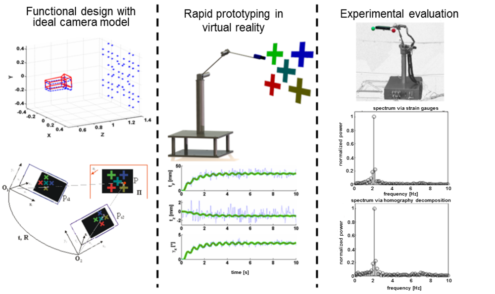
Figure 7: Design methodology for image-based functionalities.
As a part of the development process of these new approaches, the image-based oscillation detection system outlined in Figure 7 has been tested. The figure represents the algorithm: the functional design using an ideal camera model (left), the prototype implementation done in a virtual environment (center) and transfer of developed algorithms to the target system (right). The ideal camera model mimics the projective image of a pinhole camera, so that ideas and concepts can be examined first from a purely theoretical point of view. Various disturbances caused during the actual image acquisition by a camera may remain unobserved at this stage. The image recognition, feature extraction, calibration and discretization are performed in the second step in virtual reality. Here, these effects can be specifically influenced and their effects in the developed process can be evaluated. In this way, many influential factors and problems can be foreseen which reduces development time and improves the results.
The image-based oscillation damping concepts, waiving additional strain sensing, and the analysis of effects introduced by the camera and the image processing delay time are the ongoing topics in the research project.
Damped dynamics modeling
With the structural oscillations sufficiently damped by the augmented inner loop independent joint controllers, the modeling and identification of the residual arm dynamics drastically simplifies. Malzahn, J., R. F. Reinhart and T. Bertram (2014) investigate and quantitatively compare analytical and data-driven techniques for this purpose. The techniques can explain the per motor joint currents as well as the per link strain measurements in dependence on the joint angles and their temporal derivatives.
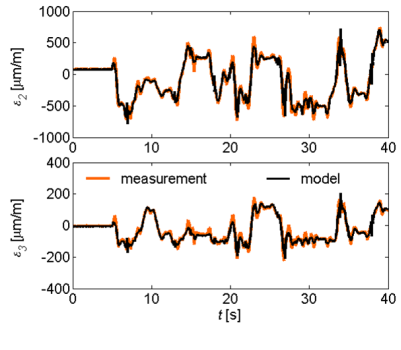
Figure 8: Damped strain dynamics identification result obtained from a motion stimulus with random steps at random time instants simultaneously realized for each joint and a payload mass of 400 g.
The key to the analytical model is the identification of a linear mapping derived between the load torque acting on the joints as well as the bending torque effecting the measured strain values. The identified mapping allows the strain gauges applied to the link surfaces to be used as load side joint torque sensors.
Next, the linear mapping can be used to model the strain referred arm dynamics with exactly the same mathematical structure as the joint torque referred equations of motion known from rigid robots. An identification result for the these strain referred dynamics is depicted in figure 8.
Physical interaction collision detection and reaction
With the damped strain dynamics identified, the intrinsic link compliance can be exploited to sense contact forces, to detect and react to accidental collisions as well as to realize intended physical human robot interaction. Figure 9 depicts the contact cube with integrated force/torque sensing capability, which serves as a reference for experiments in direct force control as well as collision detection and reaction.
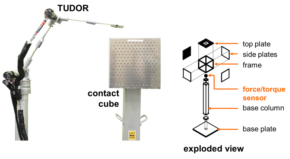
Figure 9: TUDOR and the contact cube with integrated force/torque sensor for quantitative evaluation of collision detection and reaction strategies.
The collision detection is based on the residual defined between the predicted model based generalized momentum and the generalized momentum computed from the actual strain measurements on each link. A collision is detected if any per link residual value exceeds a given threshold. The location of the collision along the arm structure can be isolated from the last link in the kinematic chain showing such a threshold violation. The residual sign provides the directional information.
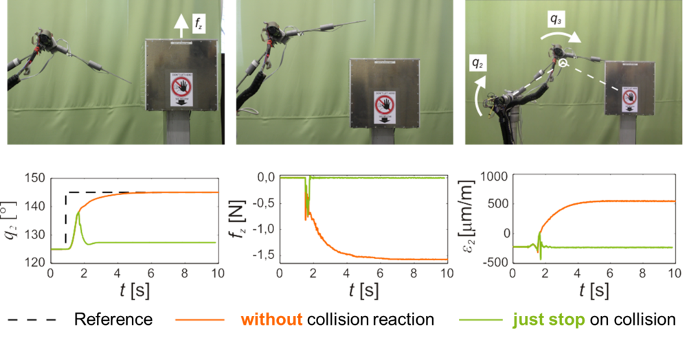
Figure 10: Collision detection and reaction results with the commanded joint configuration (top left), the initial joint configuration with the contact cube being shifted into the robot workspace (top center) and the realized collision (top right). The bottom row shows measurements for the second joint angle, the cube force as well as the link strain obtained at the second link. The reaction strategy in this example is to just stop all joint motions upon detection of a collision.
For collision reaction, various strategies are conceivable. The simplest one to just stop all joints immediately once a collision is detected. Results with this strategy during blunt impacts with the contact cube are illustrated in Figure 10.
Other collision reaction strategies are implemented by defining a desired collision admittance reflected by each joint. The admittance has the collision residual as input and a collision reaction velocity command as output. Upon collision detection the original input to the velocity controller is replaced by this collision reaction velocity. For instance, the admittance can be selected to realize an over reactive reflex motion, which causes the robot to rapidly retreat from the location of collision. Such a strategy further reduces the impulse exchanged between the robot and the environment.
In the same way an admittance can be tuned to make the robot smoothly backdriveable and enable comfortable kinesthetic reconfiguration of the arm.
The video below demonstrates collision detection and reaction experiments of sharp impacts between TUDOR and fragile objects as well as a human arm. The video closes with a demonstration of kinesthetic reconfiguration of the robot as an example for intended physical human robot interaction.
Video: Oscillation Damping, Collision Detection and Reaction for a Multi-Elastic-Link Robot Arm.
Transfer of results to conventional industrial robots
Industrial robots are intended for fast and precise manipulation of heavy payloads. The optimization of these objectives results in the bulky design of today's conventional robot arms, aiming at the maximization of precision through structural rigidity.
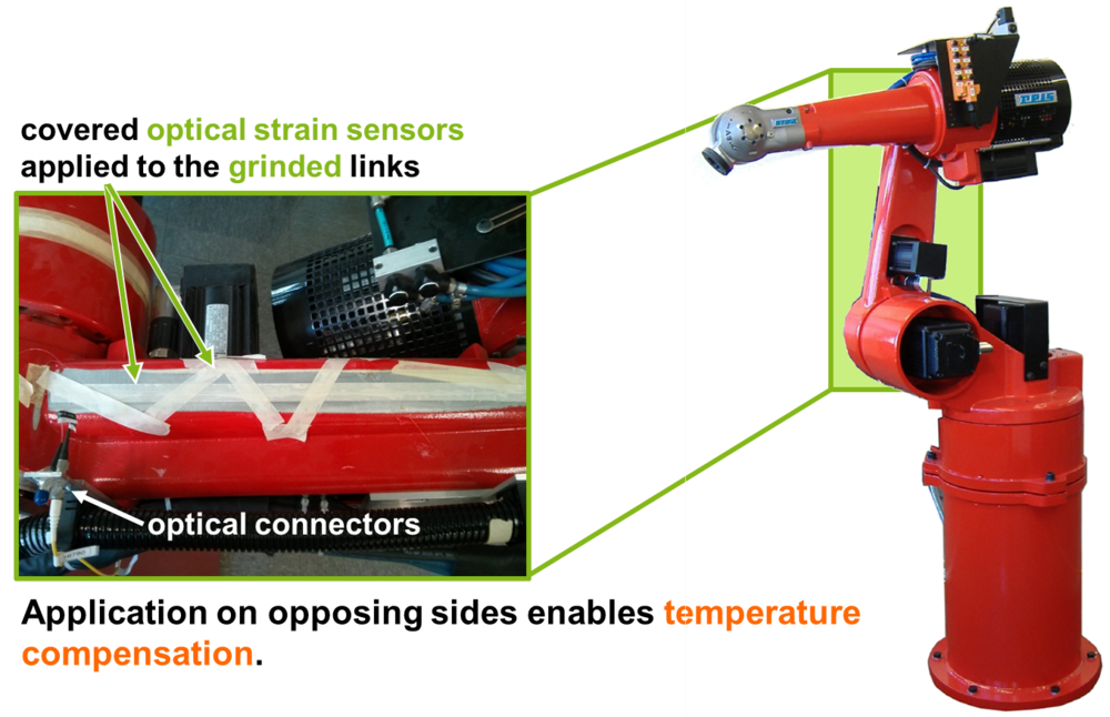
Figure 11: Conventional industrial robot equipped with Fiber Bragg Grating sensors on the links.
However, the video below demonstrates that the question, whether a robot is rigid or not depends on how close one wishes to look at it. In the video a human deflects the end effector of a typical conventional industrial robot by hand without major efforts. As a moderate manual pushes effect structural oscillations and deflections in the order of 2 mm.
The deflections and oscillations originate from a combination of the actually present joint as well as link elasticity. While the joint elasticity due to the harmonic drive gears as well as the drive belts are surely dominant, the link elasticity is also measurable using the Fiber Bragg Grating sensors described above. Figure 11 illustrates how the optical sensors are applied to the industrial robot structure.
The modeling and identification techniques for the strain referred arm dynamics developed with TUDOR can be directly transferred to the optical strain measurements on the industrial robot. This way contact forces can also be sensed with the bulky industrial arm by exploiting the present intrinsic link compliance. Similar to TUDOR the video shows that - through control algorithms - the stiff industrial robot can be made virtually backdrivable.
Video: Exploiting Link Elasticity in a Conventional Industrial Robot Arm.
MERIt: A Multi-Elastic-Link Robot Identification Dataset
The idea behind behind MERIt is to make real measurement data freely available to other researchers working in the modeling and control of elastic-link robots without having a direct access to an experimental setup.
About MERIt
During our research with the experimental platform TUDOR, a number of measurements have been collected for kinematics as well as dynamics identification. In our opinion the research in elastic link robots suffers from the very limited number of experimental setups being available in the world. Among the few existing experimental setups even fewer are multi-link arms. Most setups operate in a horizontal plane in order to eliminate the effect of gravity on the mechanism dynamics.
At the current state the control of elastic link arms is a fundamental research topic. Many promising theoretical concepts, which can be found in literature, still have to prove their value in experimental evaluations before they can enter practical applications. However, the development and maintenance of an experimental setup is a challenging, costly and time consuming technical burden coming on top of the actual scientific workload.
We hope the MERIt will be useful for other researchers. If you wish to use it, please add a reference in your publications. A reference could look like:
- Malzahn, J. and T. Bertram: MERIt - A Multi-Elastic-Link Robot Identification Dataset, Institute of Control Theory and Systems Engineering (RST), TU Dortmund, Germany. URL: http://tinyurl.com/TUDOR-MERIt , date of last check, dataset name.
The MERIt is intended to continuously develop over time. If you have access to an experimental setup we encourage you to contribute additional data to the MERIt. Any real elastic-link arm is greatly welcome. Contributions will get suitably acknowledged.
Download
The MERIt is organized in MATLAB iddata objects since MATLAB is the tool we use for the development of our models and control algorithms. All iddata objects comprise multiple realizations of the same experiment in a conveniently compact and documented data structure. However, if you do not own a recent MATLAB System Identification Toolbox license, you can access the data using Octave. Octave loads the data as structures. An alternative organization of the measurements in HDF5 files is currently under consideration. In exceptional situations we could offer to convert the data format to CSV files upon personal request.
Download: MERIt zip Archive
More details on the contents of MERIt can be found in the MERIt PDF Documentation.
We are grateful to the German Research Foundation (DFG, BE 1569/7-1) and the DAAD-MOET-project 322 for the financial support of the project
References
2016
- Alsayegh, M., F. I. Mues, J. Malzahn und T. Bertram: "Analytic Forward and Inverse Kinematics of a Multi-Elastic-Link Robot Arm", Proceedings of the joint conference of the 47st International Symposium on Robotics (ISR 2016), June 21.-22. 2016, Munich, Germany Juni 2016
- Mues, F. I., M. Alsayegh, J. Malzahn und T. Bertram: "Analytical Forward and Inverse Kinematics of a Multi-Flexible-Link Robot Arm under Gravity", DGR Tage, June 29.-30. 2016, Leipzig, Germany Juni 2016
2014
- Malzahn, J. and T. Bertram: Fractional Order Strain Feedback for Oscillation Damping of a Multi-Elastic-Link Arm Under Gravity, Proceedings of the joint conference of the 45th International Symposium on Robotics (ISR 2014) and the 8th German Conference on Robotics (ROBOTIK 2014), 2-4 June 2014, Munich, Germany.
- Malzahn, J. and T. Bertram: Collision Detection and Reaction for a Multi-Elastic-Link Robot Arm, IFAC World Congress, Cape Town (South Africa), 2014.
- Malzahn, J., R. F. Reinhart and T. Bertram: Dynamics Identification of a Damped Multi Elastic Link Robot Arm under Gravity, IEEE International Conference on Robotics and Automation, Honkong, China, 2014.
2013
- Malzahn, J. and T. Bertram: Link Elasticity in a Robot Arm - From a Problem to an Opportunity, DGR Tage, October 07.-08., München, 2013. Oktober 2013
2012
- Malzahn, J., A. S. Phung and T. Bertram: Predictive Delay Compensation for Camera Based Oscillation Damping of a Multi Link Flexible Robot, 5th International Conference on Intelligent Robotics and Applications (ICIRA), Montreal (Canada), Oct. 3-5, 2012.
- Malzahn, J., A. S. Phung and T. Bertram: Scene Adaptive RGB-D Based Oscillation Sensing for a Multi Flexible Link Robot Arm in Unstructured Dynamic Environments, IEEE/RSJ International Conference on Intelligent Robots and Systems (IROS), Vilamoura (Portugal), Oct. 7-12, 2012.
- Malzahn, J., A. S. Phung and T. Bertram: A Multi-Link-Flexible Robot Arm Catching Thrown Balls. 7th German Conference on Robotics, 21./22.05.2012 ,pp. 411-416.
- Malzahn, J. and T. Bertram: Einsatz eines RGB-D-Sensors zur schwingungsgedämpften Positionierung eines gliedelastischen Roboterarms, Regelungstechnisches Kolloquium, Boppard, Februar 2012.
- Malzahn, J., A. S. Phung, F. Hoffmann and T. Bertram: Bildbasierte Regelung eines gliedelastischen Roboterarms mit einem RGB-D-Sensor, at - Automatisierungstechnik: Vol. 60, No. 5, pp. 246-259. doi: 10.1524/auto.2012.0992, 2012.
2011
- Phung, A. S., J. Malzahn, F. Hoffmann and T. Bertram: Datenbasierte Modellierung der Kinematik eines dreigliedrigen elastischen Roboterarms, Seiten 187-202 Proceedings 21. Workshop Computational Intelligence, Hrsg. F. Hoffmann, E. Hüllermeier, Dortmund, Dezember 2011.
- Malzahn, J., A. S. Phung, F. Hoffmann and T. Bertram: Vibration Control of a Multi-Flexible-Link Robot Arm under Gravity, In IEEE International Conference on Robotics and Biomimetics, Phuket (Thailand),07.-11.12.2011, pp. 1249-1254.
- Phung, A. S., J. Malzahn, F. Hoffmann and T. Bertram: Data Based Kinematic Model of a Multi-Flexible-Link Robot Arm for Varying Payloads, In IEEE International Conference on Robotics and Biomimetics, Phuket (Thailand), 07.-11.12.2011, pp. 1255-1260.
- Malzahn, J., A. S. Phung, F. Hoffmann, M. Ruderman and T. Bertram: Modellfreie Schwingungsdämpfung eines eingliedrigen elastischen Roboterarms unter Gravitationseinfluss, Fachtagung Mechatronik 2011, Dresden, Deutschland, 31.03.-01.04.2011, ISBN 978-3-00-033892-2, S. 89-94.
2010
- Malzahn, J., M. Ruderman, A. S. Phung, F. Hoffmann and T. Bertram: Input Shaping and strain gauge feedback vibration control of an elastic robotic arm, 2010 IEEE Conference on Control and Fault Tolerant Systems (Systol'10), pp. 672-677, Nice, France.
- Malzahn, J., A. S. Phung, R. Franke, F. Hoffmann and T. Bertram: Markerless Visual Vibration Damping of a 3-DOF Flexible Link Robot Arm, In Proceedings of the joint conference of the 41st International Symposium on Robotics (ISR 2010) and the 6th German Conference on Robotics (ROBOTIK 2010), 401-408; 7-9 June 2010, Munich, Germany.
2009
- Franke, R., T. Nierobisch, J. Malzahn, F. Hoffmann und T. Bertram: Simulation und Verifikation einer bildbasierten Schwingungsdetektion zur Regelung des mehrgliedrigen elastischen Leichtbauarms TUDOR, Technische Wissenschaften, No. 4, ISSN 0321-2653, S. 27-33 2009
- Malzahn, J., R. Franke, F. Hoffmann and T. Bertram: Modellierung und Regelung eines mehrgliedrigen elastischen Roboterarms, VDI Automation 2009, Fachtagung Baden-Baden, VDI-Berichte
Juni 2009 - Franke, R., J. Malzahn, T. Nierobisch, F. Hoffmann and T. Bertram: Vibration control of a multi link flexible robot arm with Fiber-Bragg-Grating-Sensors, IEEE International Conference on Robotics and Automation, Kobe, Japan, May 2009.
2008
- Franke, R., F. Hoffmann and T. Bertram: Observation of Link Deformations of a Robotic Manipulator with Fiber Bragg Grating Sensors , IEEE/ASME International Conference on Advanced Intelligent Mechatronics (AIM 2008), Xi'an, China.
- Franke, R., T. Nierobisch, F. Hoffmann and T. Bertram: Entwurf eines modularen elastischen Handhabungssystems mit drei Freiheitsgraden zur bildbasierten Regelung, Robotik 2008, Fachtagung München, VDI-Berichte Nr.2012. Düsseldorf: VDI-Verlag, S. 329-332.
- Franke, R., T. Nierobisch, F. Hoffmann and T. Bertram: Schwingungsdetektion eines elastischen Arms mittels Faser-Bragg-Gitter und visueller Sensorik, Sensoren und Meßsysteme 2008, 14. Fachtagung Ludwigsburg, VDI-Berichte Nr.2011. Düsseldorf: VDI-Verlag, S. 737-746.
- Franke, R. and T. Bertram: Untersuchungen zum Einsatz von Faser-Bragg-Gitter-Sensoren in der Robotik, 42. Regelungstechnisches Kolloquium, Boppard, Februar 2008.
2007
- Franke, R., M. Sternke and T. Bertram: Messung und Modellierung der Verformung von Roboterkörpern mit Faser-Bragg-Gitter-Sensoren, Internationales Forum Mechatronik (ifm2007), Winterthur, Schweiz
September 2007